
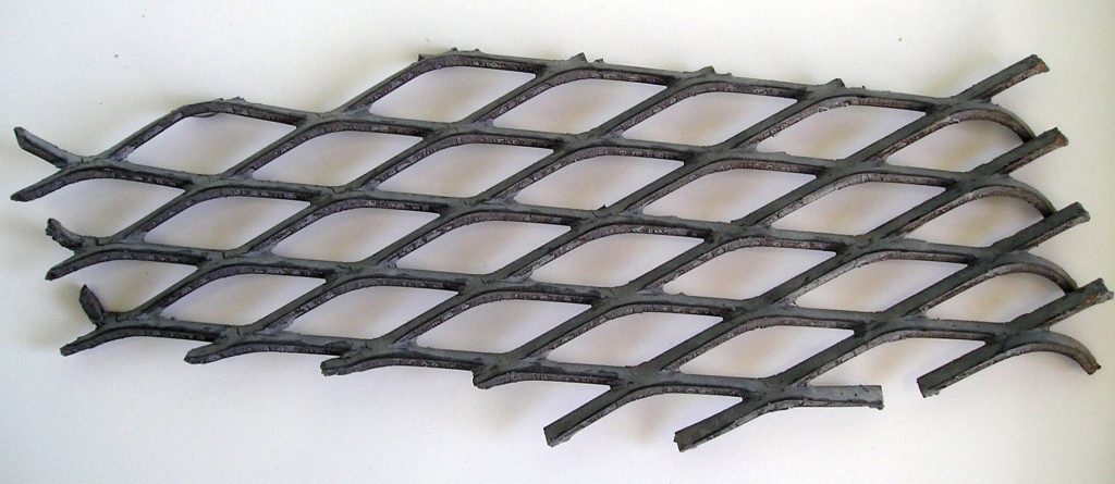
This guide will show how to model sheets of Expanded Metal in FreeCAD, without slowing (or killing) FreeCAD.

In our last guide, we looked at how to get a granular view of the size (in bytes) of each layer in a FreeCAD file — so we could figure out which object was causing the file to be so large and slow. We found that 90% of the file’s (uncompressed) MemSize was being caused by just one item: a 95 cm x 68 cm sheet of Expanded Metal.
.jpg)
Unfortunately, rendering mesh objects (like Expanded Metal) in any CAD software can cause enormous lag in the app.
This article is part of a 3-part series:
- Part 1/3: Troubleshooting Large FreeCAD File Sizes
- Part 2/3: Optimizing Expanded Metal Mesh in FreeCAD
- Part 3/3: Life-Line v2025.10 Released
Optimization Attempt #1: Array
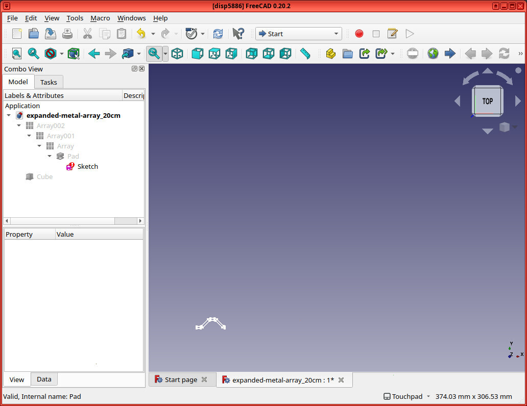
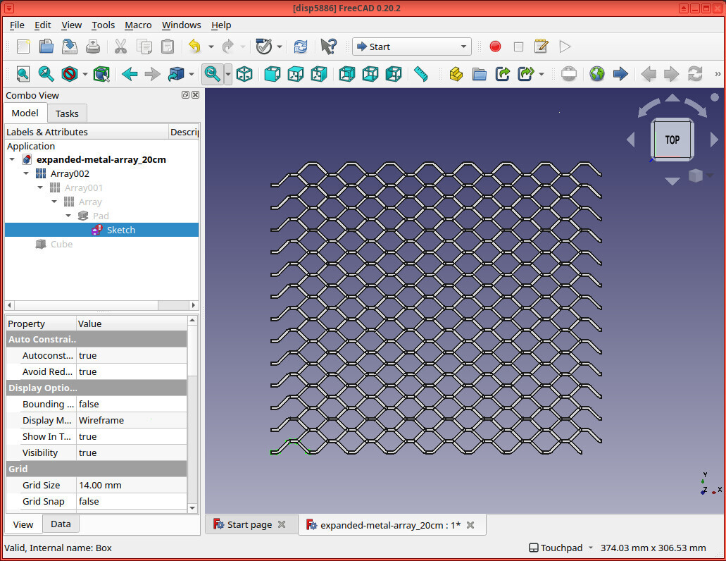
My first thought was: rather than having one large sheet of Expanded Metal, let’s just simplify this object to its lowest common denominator: a sketch (and extrusion) of a single “diamond”. Then we’ll use arrays to clone the as-simple-as-possible shape in two dimensions, as needed.
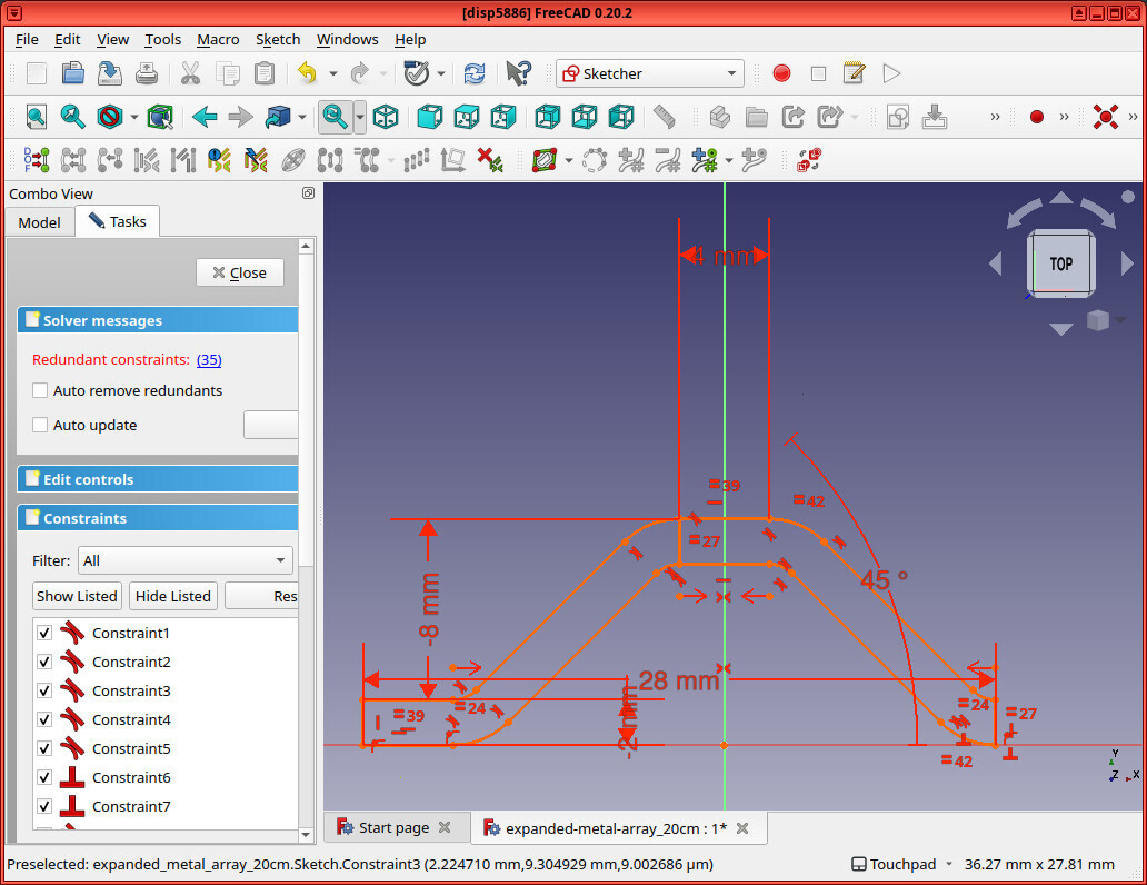
Because, FreeCAD should then have some magic to be able to store just the item once, and it’ll make things super small and fast, right?
After some searching on the FreeCAD forums, I was able to find this post, where someone had created exactly that: a simple sketch of a single “link”, and then they used arrays to expand it in both directions. The file with the Expanded Metal sheet modeled in this way was only 56 KB.
I wanted to see how well this idea would scale. My first thought was to create three files:
- An expanded metal mesh that’s 1 meter x 1 meter
- An expanded metal mesh that’s 10 meters x 10 meters
- An expanded metal mesh that’s 100 meters x 100 meters
…but that plan quickly failed. I couldn’t even render the 10 meter x 10 meter expanded metal mesh without my poor computer thrashing (and nearly crashing).
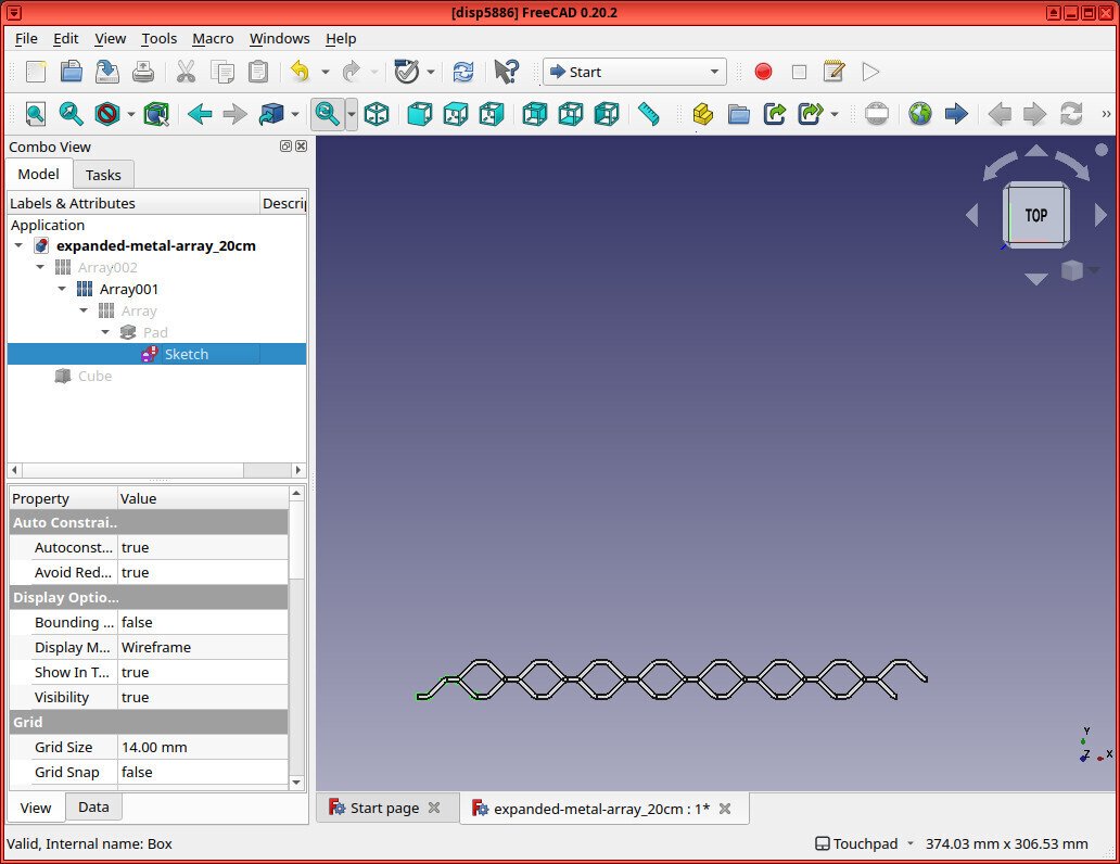
Instead, I created the following:
- A FreeCAD file with an expanded metal mesh measuring approximately 10 cm x 10 cm
- A FreeCAD file with an expanded metal mesh measuring approximately 20 cm x 20 cm
- A file with an expanded metal mesh measuring approximately 40 cm x 40 cm
- And one measuring ~ 80 cm x 80 cm
I tried to create one with an expanded metal mesh array measuring 160 cm x 160 cm, but FreeCAD crashed.
While it was obvious that my idea to “optimize” rendering an Expanded Metal Mesh in FreeCAD by using a super-simple sketch + array was NOT going to scale, I wanted to understand how bad this idea was.
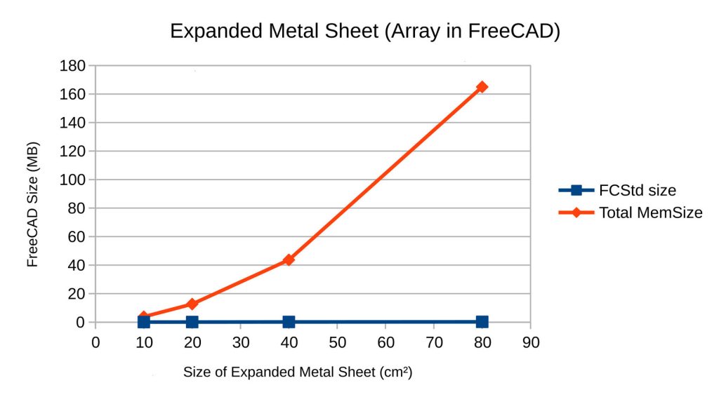
The chart below shows the following for each file:
- .FCStd Size = The total (compressed) .FCStd file-size on-disk (in MB)
- Total MemSize = The total (uncompressed) MemSize of the file (in MB)
| File | .FCStd Size (MB) | Total MemSize (MB) |
|---|---|---|
| 10cm | 0.56 | 3.75 |
| 20cm | 0.84 | 12.67 |
| 40cm | 0.13 | 43.65 |
| 80cm | 0.22 | 165.01 |
| 160cm | crashed | – |
Graphed, it appears the MemSize grows at an exponential rate.
Optimization Attempt #2: Hatch
After further digging, I learned that this is a common issue in all CAD software. Because of this, professional engineers (even those poor souls who have to use AutoCAD) typically do not render (Expanded Metal) meshes. Instead, they put a placeholder solid sheet in its place, with an information fragment added to the drawing that describes the type of material.
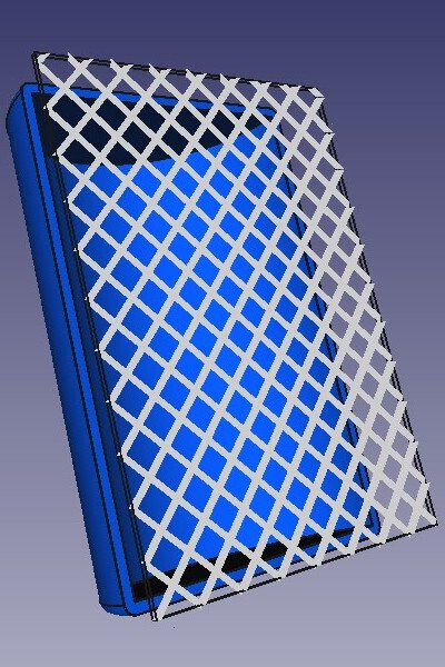
But I wondered if there was some middle-ground — some way we could draw a solid and “color” it with some sort of bitmap to make it clear that it’s a placeholder. And I found one: a hatch
A hatch is a simple 2D pattern that gets drawn over a solid. I quickly found that I could draw a “diamond” pattern hatch over the solid with thick silver lines and set the solid to be transparent. The result: you get some sheet that looks like it’s made of some diamond-patterned metal mesh, but the shape and size of the holes is very far from accurate.
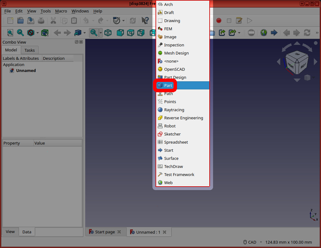
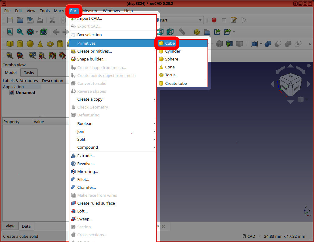
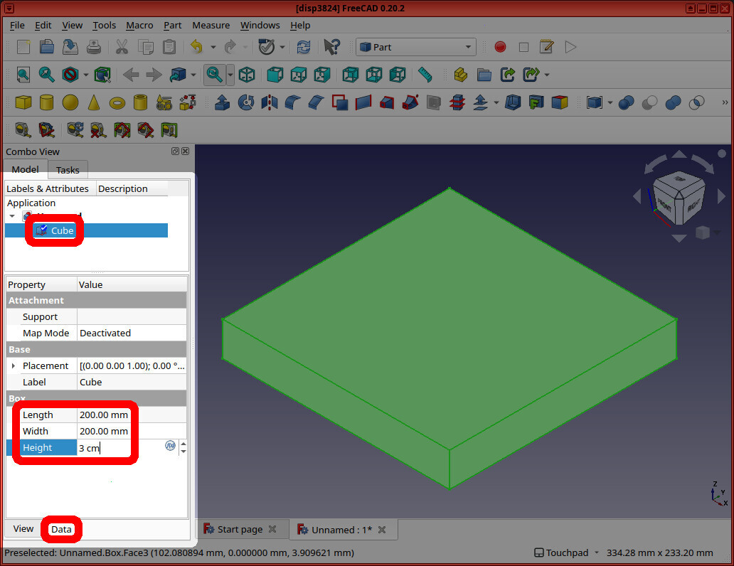
To do this, I first created a solid sheet by switching to the “Part” workbench, and clicking Part -> Primitives -> Cube. Then I changed the cube’s dimensions to 20 cm x 20 cm x 3 mm.
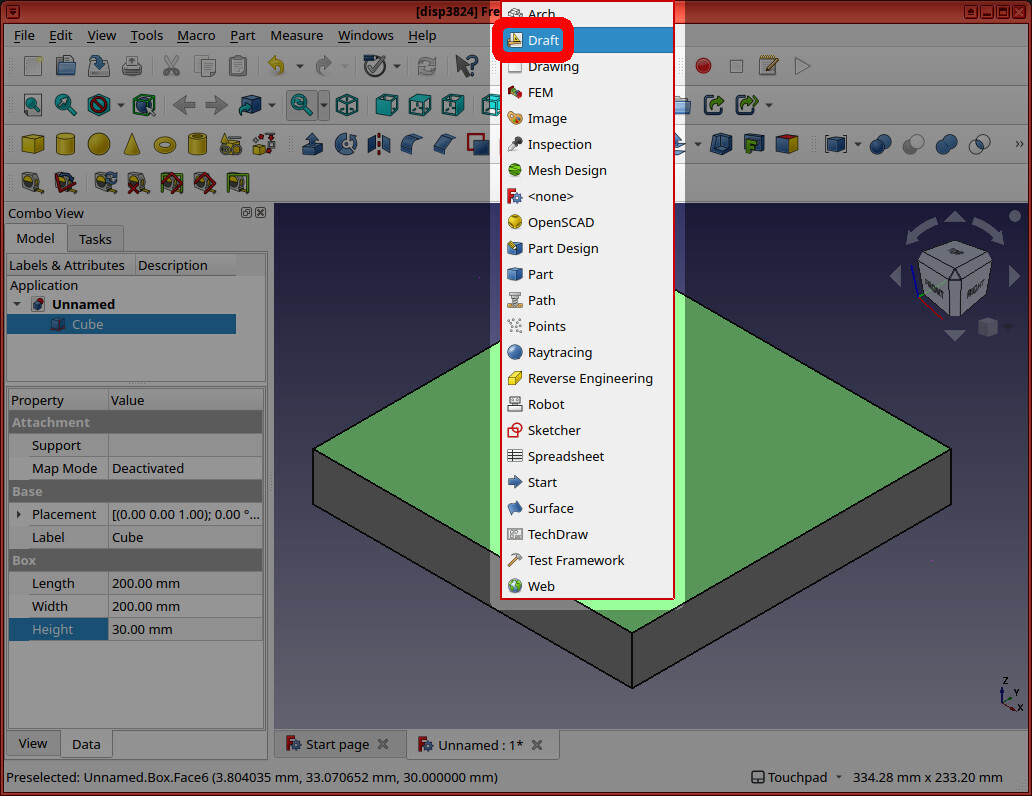
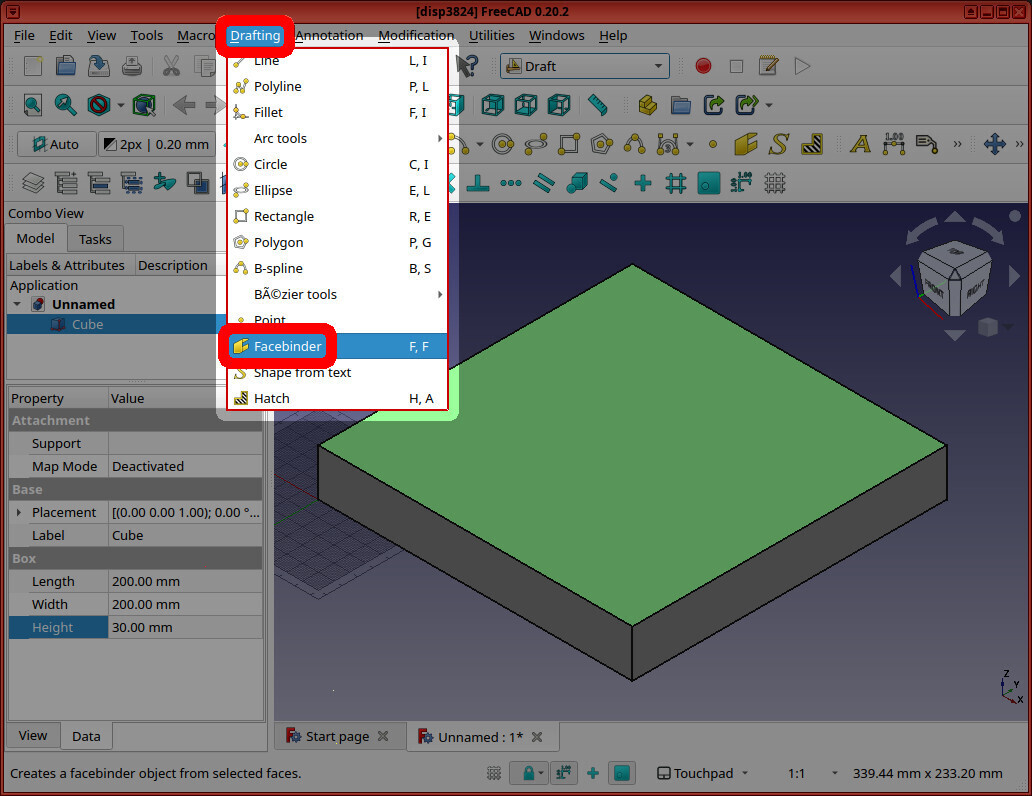
To draw the “hatch” on the top plane of our cube/sheet, I then I switched to the Draft Workbench. I then selected the top plane of our cube, and clicked “Drafting -> Facebinder”.
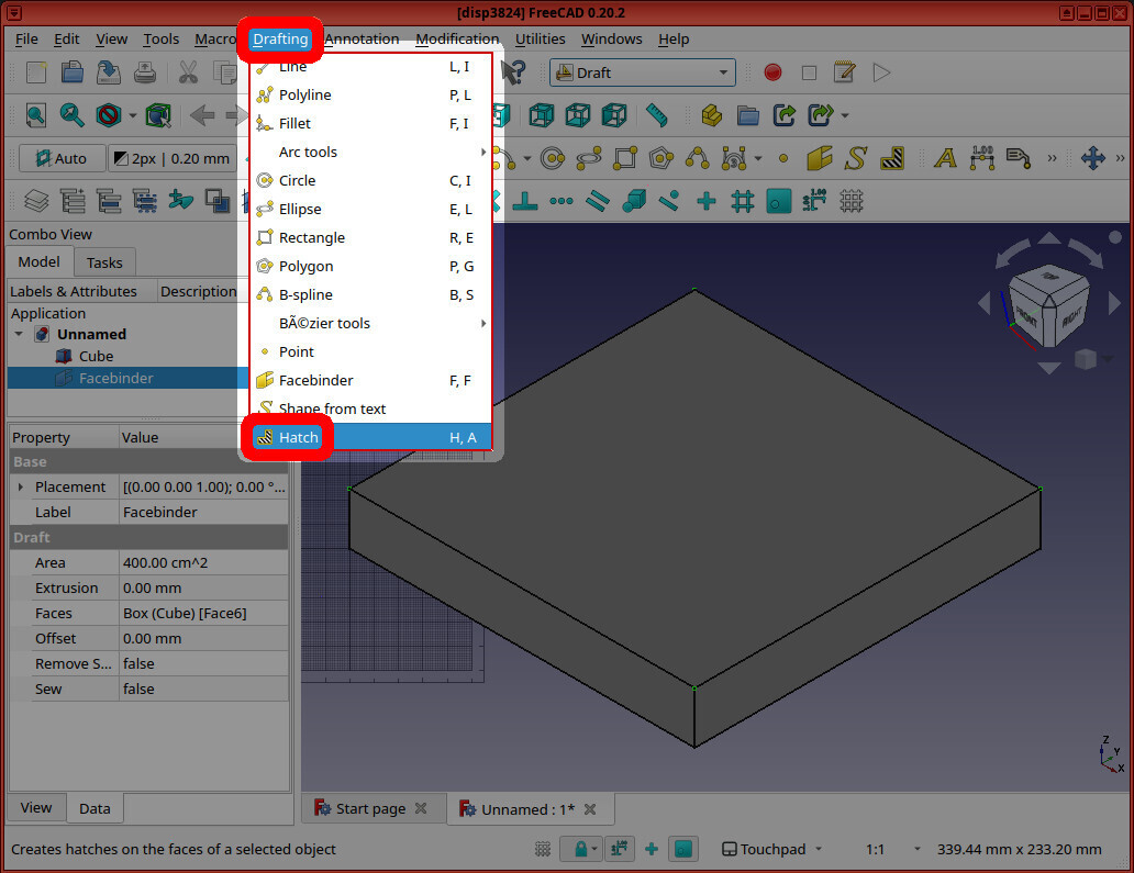
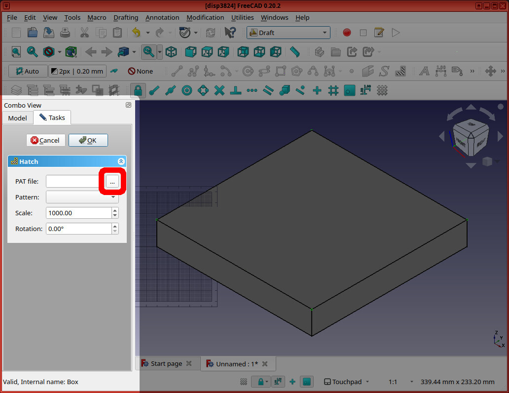
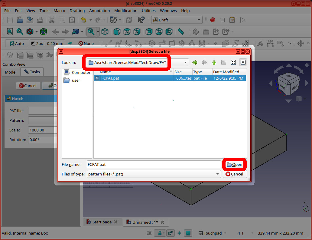
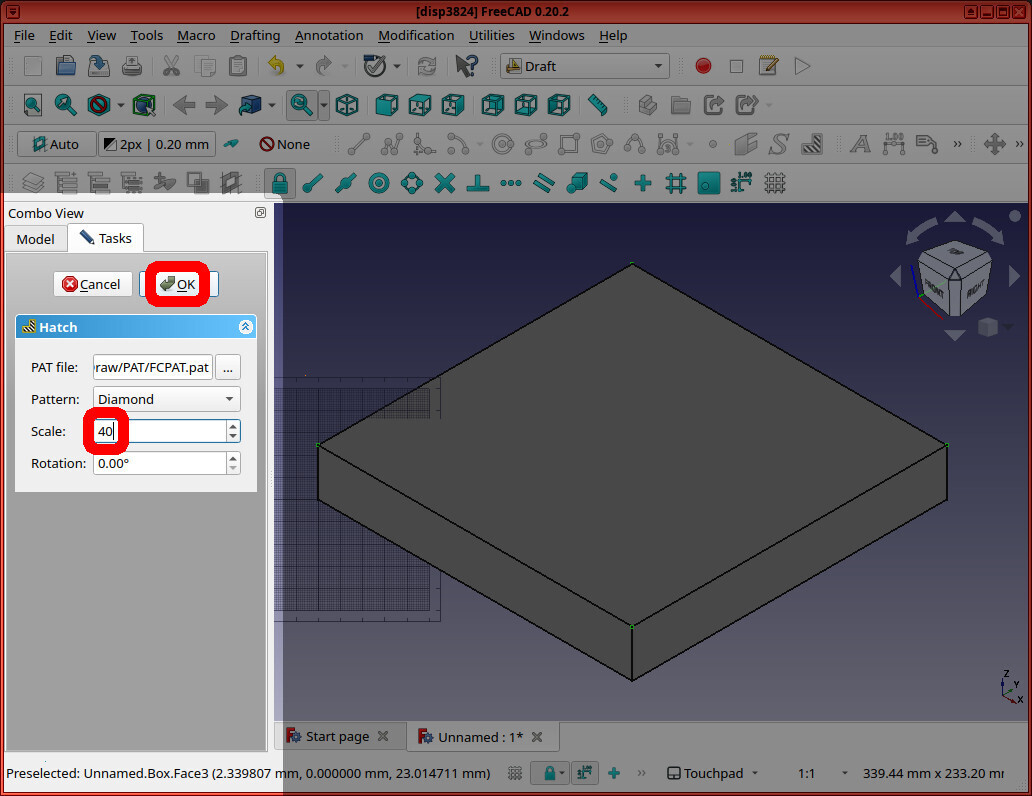
Then I clicked “Drafting” -> “Hatch”. Browse to the FreeCAD progam folder (eg /usr/share/freecad) and select data/Mod/TechDraw/PAT/FCPAT.pat. I chose the “Pattern” = “Diamond”, set the “scale” to “40”, and pressed “OK”.
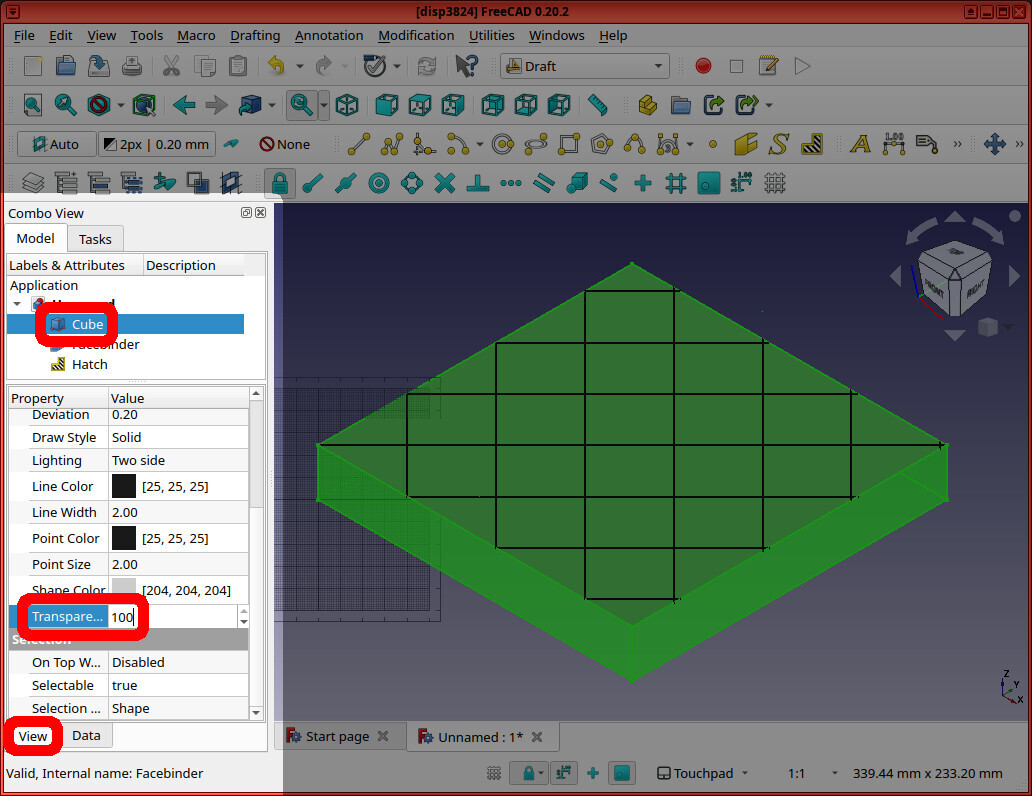
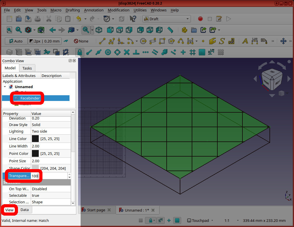
Next, we can make the non-hatch-lines transparent by selecting the “Cube”, clicking the “View” tab, and changing “Transparency” from “0” to “100”. Do the same for the “Facebinder” object.
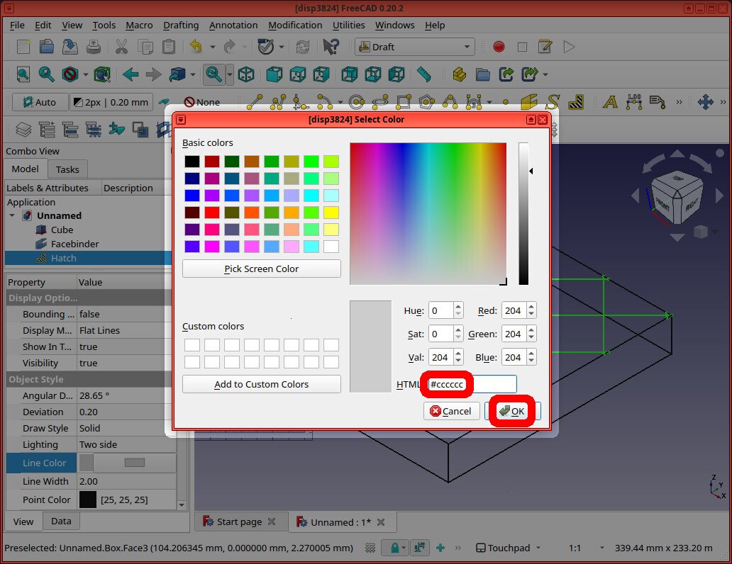
And we can make the lines appear “metalic” in color, by selecting the “Hatch”, and setting the “Line Color” to “#cccccc”
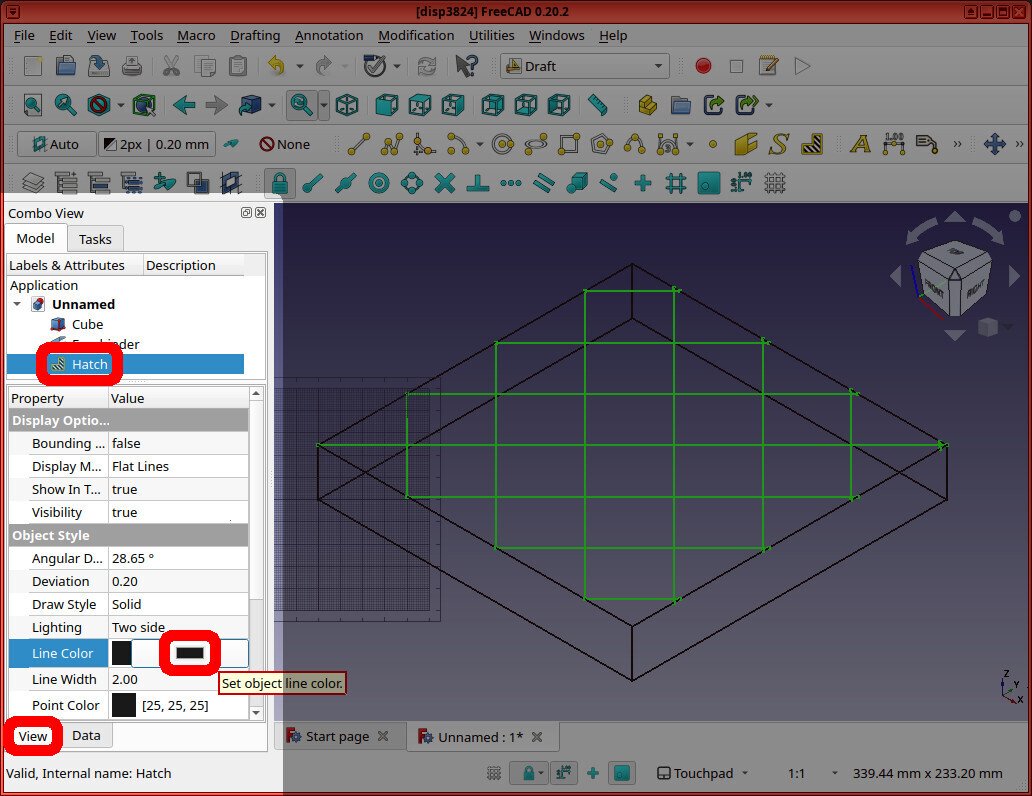
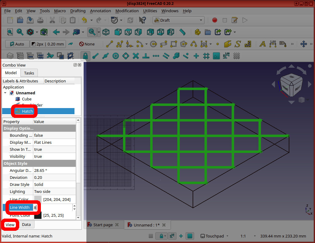
And you can make the lines “thicker” by changing the Hatch object’s “Line Width” to “8”.
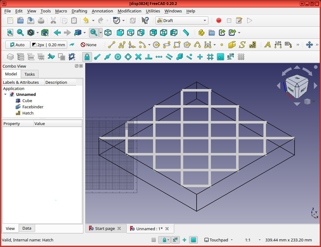
Finally, we have a 20 cm x 20 cm sheet (that’s 3 cm thick) that looks close-enough to a sheet of expanded metal — but whoose size is magnitudes less (in bytes)
You can experiment by changing the hatch’s Scale (the frequency of the lines = the size of the holes in the mesh) and/or by changing the hatch’s Line Width.
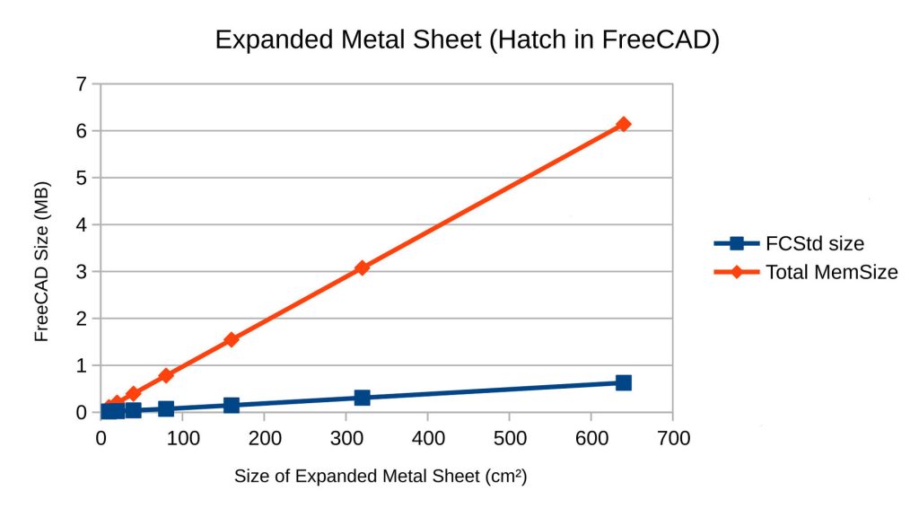
As above, I repeated this for different size sheets. Doubling the size of the sheet every time, I was able to make it to a 640 cm x 640 cm sheet. Attempting to create a 1,280 cm x 1,280 cm (12 meter x 12 meter) sheet did, unfortunately, crash FreeCAD.
| File | .FCStd Size (MB) | Total MemSize (MB) |
|---|---|---|
| 10cm | 0.016 | 0.110 |
| 20cm | 0.024 | 0.205 |
| 40cm | 0.040 | 0.395 |
| 80cm | 0.072 | 0.780 |
| 160cm | 0.148 | 0.155 |
| 320cm | 0.308 | 3.075 |
| 640cm | 0.628 | 6.141 |
| 1,280cm | crashed | – |
The graph shows linear growth, and the MemSize is on the order of three magnitudes smaller
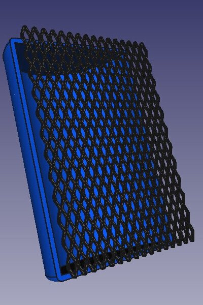
Conclusion
In the end, arrays of expanded metal objects in FreeCAD don’t make sense. It’s better to just make a solid object and “hatch” it.
This is clear when we compare the (compressed) .FCStd file size and the (uncompressed) MemSize of (left) the simplified array model vs (right) the hatched solid model:


Here’s a list of the pros & cons of using a hatch instead of an array to represent an Expanded Metal sheet in FreeCAD:
Pros
- Smaller (compressed) file sizes
- Smaller (uncompressed) object MemSize
- Much easier to render, view, and update in FreeCAD
- Lowers barrier-of-entry for other collaborators
Cons
- Imprecise 3D model
- Requires supplementary specification in object’s documented BOM (Bill of Materials) for actual dimensions of object
Limitations
Obviously using hatches is significantly better than modeling an array of “links” to create a sheet of Expanded Metal in FreeCAD. But there are still limitations..
While I was able to create a 3D sheet of hatched Expanded Metal 6.4 meters x 6.4 meters, FreeCAD does still crash when I try to double it (to 12.8 meters x 12.8 meters).
If you know of a better way to model Expanded Metal in FreeCAD, please let us know.
Further Reading
- Troubleshooting Large FreeCAD File Sizes
- How to simplify expanded metal mesh screen? FreeCAD Forums
- One dimensional draft hatch FreeCAD Forums
- expanded-metal-hatch-freecad git repo (with spreadsheets and freecad files used in this article)
Who is Eco-Libre?
Eco-Libre is a volunteer-run project that designs libre technology for sustainable communities.
Eco-Libre’s mission is to research, develop, document, teach, build, and distribute open-source technology that sustainably enfranchises communities’ human rights.
– Eco-Libre’s mission statement
We aim to provide clear documentation to build low-cost machines, tools, and infrastructure for people all over the world who wish to live in sustainable communities with others.
If you’d like to help Eco-Libre reach our mission to enfranchise sustainable communities’ human rights with libre technology, please contact us to get involved 🙂
Please enter your email address below for updates from the Eco-Libre Team.